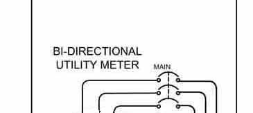
Utility Meter
This is the normal utility revenue meter used for billing and generally sealed to prevent tampering. In most cases a bi-directional electronic meter will be installed.
Details
Typical Photos
Main Service Entrance Breaker
Before the PV system was installed, the main breaker most likely matched the rating of the busbars in the main distribution panel.
Due to the possibility of overloading the busbars, the allowable ratings of the main breaker and the PV AC breaker need to be coordinated as described under Details
Details
Switch Selection Info
Typical Photos
NEC Code references
Main Distribution Panel
This is the point of connection for a PV system, on the load side of the main breaker.
The ratings of the busbar in this panel is key to the allowable PV and main breaker sizes as detailed elsewhere in this website.
Detailed Description
Busbar
Typical Photos
NEC Code references
Troubleshooting
If the PV system is connected as shown on this diagram such that the current from the PV system will pass through the main breaker, the sum of the ratings of the main breaker and the PV breaker must not exceed 125% of the rating of the main bus in the distribution panel and the PV breaker must be located on the buss on the opposite end from the connection to the main breaker. Otherwise, the sum of the ratings of the main breaker and the PV breaker must not exceed 100% of the rating of the main bus in the distribution panel.
Detailed Description
Breaker Criteria
Typical Photos
NEC Code
Troubleshooting
PV AC Breaker
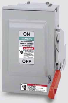
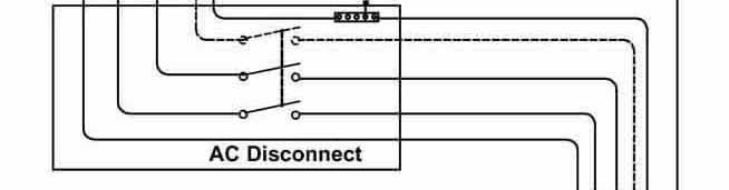
AC Disconnect
A means for disconnecting all ungrounded conductors of the inverter from the building wiring is required. There may be more than one switch if the inverter is not located near the main panel. Most utilities require a visible blade safety switch for their exclusive use.
Detailed Description
Switch Selection Info
Typical Photos
NEC Code references
Troubleshooting
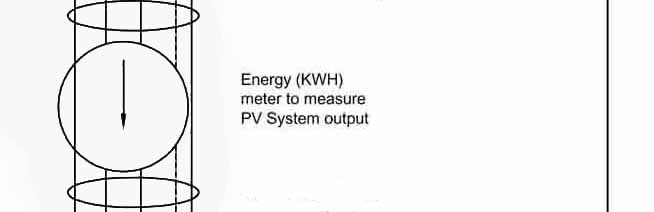
PV Energy Meter
This is the usual location of a PV Energy Meter that measures the kilo-Watt-Hours of energy produced by the Inverter. This meter is not required by the NEC, but is often required by the electric utility, especially if rebates or incentives are involved.
Detailed Description
KWH Meter Size
Typical Photos
NEC Code references
Troubleshooting
AC Wiring
Voltage drop (actually a voltage rise) from the main panel is more important on the AC side because voltage limits set in the inverter are the same as the limits for electrical service. If the utility voltage is close to the high limit for utility service and the wiring is long or smaller gauge, the inverter can shut down and energy will be lost.
Detailed Description
Wire Size Calculation
NEC Code references
Troubleshooting
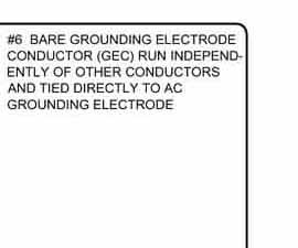
Grounding Electrode Conductor (GEC)
The circuit(s) that connects the point(s) of AC & DC system bonding, the point where the grounded conductor is grounded in the inverter, to the premises grounding electrode system.
More Info on Grounding
Wire Size Calculation
Typical Photos
NEC Code references
Troubleshooting
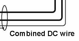
Combined DC Wiring
If there is a separate DC Combiner, the currents will be higher and the ratings of all components carrying this current will have to selected for the higher current. The procedure is the same as shown on the DC Wiring link (top left of this diagram).
Detailed Description
Wire Size Calculation
NEC Code references
Troubleshooting
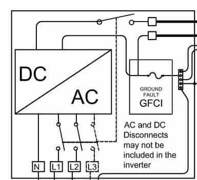
Inverter
The inverter is the heart of the PV system. The inverter converts the high DC power from the PV array into utility compatible AC power. Most inverters are microprocessor based and have a digital display and several indicators of inverter operation.
Detailed Description
Inverter Selection Info
Typical Photos
NEC Code references
Troubleshooting
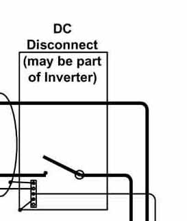
DC Disconnect
Installing and servicing a PV system requires a switch or other means to disconnect the strings of PV modules from the inverter. This switch may be included within or attached to the inverter or DC Combiner.
Detailed Description
Disconnect Ratings
Typical Photos
NEC Code references
Troubleshooting
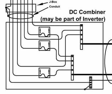
DC Combiner
When a PV system has multiple strings of PV modules connected to one inverter, there is a need to protect each string from possible damaging reverse current from the parallel strings. The combiner may be part of the inverter.
Detailed Description
DC Combiner Specification
Typical Photos
NEC Code references
Troubleshooting
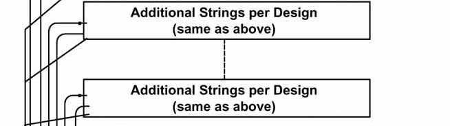
Additional PV Array Strings
A PV system may have many strings of PV modules connected to one inverter.
Detailed Description
Parallel String Calculation
NEC Code references
Troubleshooting
Grounding the PV System
All conductive parts of the PV array and nearby other conductive surfaces (metal roofing, flashings, etc.) need to be properly grounded.
The electrical wiring must also be solidly grounded or use other approved methods of providing safety. This is covered as part of the inverter discussion.
Detailed Description
Ground Wire Size
Typical Grounding Photos
NEC Code references
Troubleshooting
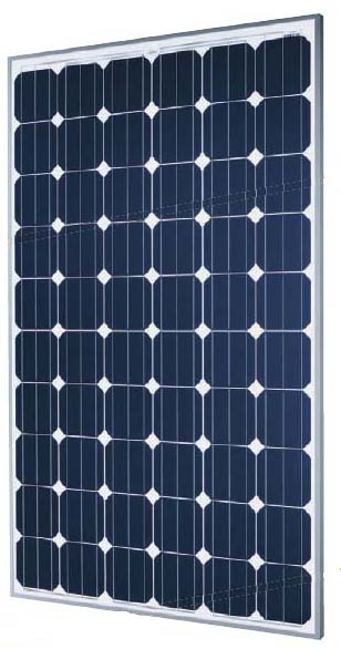
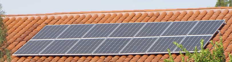
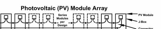
PV Modules
The PV modules are the heart of the PV system. The modules are connected in series strings according to the specifications of the inverter.
Detailed Description
Required Calculations
Typical Photos
NEC Code references
Troubleshooting
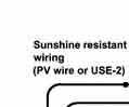
PV Wiring
The use of the correct wire type is important for PV arrays. The wire must be rated as "Sunshine Resistant". Typical types are USE-2 and the newer PV wire type. Select a wire based on system voltage (i.e. up to 600V and Up to 1000V).
Detailed Description
Wire Size Calculation
Typical Photos
NEC Code references
Troubleshooting
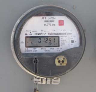
Typical Utility KWH Meter
Utility Revenue Meter
If there are any questions concerning the service, the serial number of the existing meter may help identify the specific service.
Main Breaker
No PV specific references
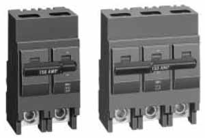
Typical Main Breaker-
These are usually 125A or higher and do not snap in.
Main Breaker
The PV AC breaker must be suitable for back feed (not marked Line/Load on the terminals).
If the breaker was downsized for the 120% rule, a label is required stating that the breaker was reduced and must remain reduced.
Main Service Entrance Breaker- Details
If the PV system is connected as shown on this diagram such that the current from the PV system will pass through the main breaker, the sum of the ratings of the main breaker and the PV breaker must not exceed 125% of the rating of the main bus in the distribution panel and the PV breaker must be located on the buss on the opposite end from the connection to the main breaker. Otherwise, the sum of the ratings of the main breaker and the PV breaker must not exceed 100% of the rating of the main bus in the distribution panel.
If the PV system is connected between the utility meter and the main breaker, the connection is called a supply side connection and the PV breaker can be rated as high as the service rating if the other equipment is properly rated for this service.
Main Distribution Panel
Troubleshooting
Visual inspection is the most effective method for troubleshooting/checking the distribution panel wiring.
Inspect all visible connections; pull on the grounding cable to make sure that lugs are firmly attached. Check that all breakers are fully seated and that all terminals are tight.
Main Distribution Panel
NEC Requirements
ARTICLE 705
Interconnected Electric Power
Production Sources
(whole article applies)
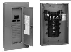
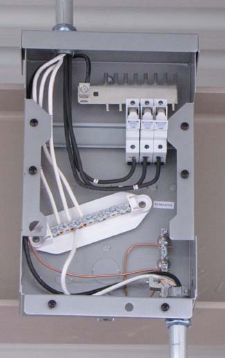
Typical Distribution Panel - The busbars are within the dark center assembly on the right photo.
Main Distribution Panel
This is generally considered a given, being in service before the PV system was installed. However, replacement busbar assemblies with upgraded ratings are available to fit many standard panels. A popular upgrade is the replace 200A busbars with 225A busbars to allow higher rated PV breakers.
Main Distribution Panel
If the PV system is connected as shown on this diagram such that the current from the PV system will pass through the main breaker, the sum of the ratings of the main breaker and the PV breaker must not exceed 125% of the rating of the main bus in the distribution panel and the PV breaker must be located on the buss on the opposite end from the connection to the main breaker. Otherwise, the sum of the ratings of the main breaker and the PV breaker must not exceed 100% of the rating of the main bus in the distribution panel.
PV AC Breaker
Troubleshooting
Visual inspection is the most effective method for troubleshooting/checking the AC wiring.
Inspect all visible connections; pull on the grounding cable to make sure that lugs are firmly attached. Conduits with circuits over 250 volts must be grounded either by ground bushings or connectors on metallic enclosures in non-concentric knock outs.
Inspect conduit couplings for possible separation.
PV AC Breaker
NEC Requirements
ARTICLE 705
Interconnected Electric Power
Production Sources
(whole article applies)
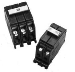
Typical Circuit Breakers
PV AC Breaker
The PV AC breaker must be suitable for back feed (not marked Line/Load on the terminals).
The lowest rating for the breaker is 125% of the labeled “Maximum Output Current” rating of the inverter, rounder up to the next standard value. The maximum rating for the breaker is listed on the inverter label and must not be exceeded.
Only breakers specifically listed for use on a specific brand of busbar should be used.
PV AC Breaker
Placement of the PV AC breaker in the distribution panel is important. If the PV AC breaker is located on the opposite end of the busbar in the main electrical panel, the allowable sum of the PV breaker rating and the main breaker rating can be as high as 125% of the rating of the busbar. Otherwise the allowable sum is 100% of the busbar rating and the main breaker will have to be downsized in order to be able to connect the PV system.
AC Disconnect Switch
Troubleshooting
AC Disconnect Switch may contain fuses that are blown, or loose connections that have burnt or opened.
Make sure that the safety switch is wired correctly with the top terminals connected to the utility so that when the switch is opened, the blades should be de-energized.
Check that the disconnect enclosure is grounded and that any conduits and ground bushings on the conduits (needed if a concentric knockout with remaining larger sizes is used in a system over 250 volts).
AC Disconnect Switch
NEC rrequirements
690.15 Disconnection of Photovoltaic Equipment
690.16 Fuses
690.17 Disconnect Type.
ARTICLE 705
Interconnected Electric Power
Production Sources
(whole article applies)
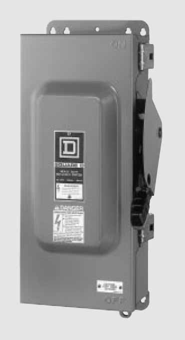
AC Disconnect Switch
AC Disconnect Switch
The AC Disconnect Switch must be rated for the service voltage, required ampacity (generally 125% of the rated output of the inverter, but some switches are ‘full’ rated and the AHJ may allow a switch to be used for currents up to the rated output of the inverters), enclosure type (indoor/outdoor, etc.), and interrupt rating.
AC Disconnect Switch
One of the main requirements of the AC Disconnect Switch is that it be readily accessible by the serving utility and have provisions to be locked off. Some utilities require an un-fused disconnect for their exclusive use, often requiring a second fused disconnect if the available fault current exceeds 10,000 amps.
In some cases the switch will be part of the inverter.
These safety switches must be secured for safety reasons such that a key or tool is needed for access due to the live circuits inside.
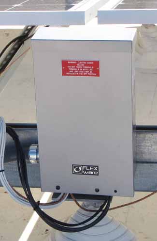
The AC Disconnect Switch must be labeled with both its use (UTILITY DISCONNECT) and the following warning:
WARNING
ELECTRIC SHOCK HAZARD
DO NOT TOUCH TERMINALS.
TERMINALS ON BOTH THE LINE AND LOAD SIDES
MAY BE ENERGIZED IN THE OPEN POSITION
Solar kWh Meter
Troubleshooting
Generally not involved in troubleshooting except as a check on PV system output compared to specifications.
Solar kWh Meter
NEC rrequirements
Not a NEC requirement, but all the requirements for conductors, grounding, rating, etc. apply.
Solar kWh Meter
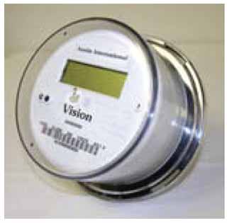
Solar kWh Meter
There are three basic attributes of these meters:
Enclosure (Indoor/Outdoor)
Security type (ring or ringless – consult utility)
Ratings (voltage, amps)
Generally meters up to 200A are self-contained, above 200A CTs (current transformers) are used.
Solar kWh Meter
This is an optional meter used for measuring the energy produced by the PV system.
In most cases this will be a meter like the main utility meter. If rebates or performance based incentives are involved, this meter will be supplied by the utility and sealed.
AC Wiring
Troubleshooting
Visual inspection is the most effective method for troubleshooting/checking the AC wiring.
Inspect all visible connections, pull on the grounding cable to make sure that lugs are firmly attached. Conduits with circuits over 250 volts must be grounded either by ground bushings or connectors on metallic enclosures in non-concentric knock outs.
Inspect conduit couplings for possible separation.
AC Wiring
NEC rrequirements
ARTICLE 705
Interconnected Electric Power
Production Sources
(whole article applies)
AC Wiring
If the cable gauge is too small for the combination of current and distance, the voltage rise of the inverter over the voltage at the service entrance will increase. At that point the inverter must cease operation per the limits in UL 1741. After a few minutes most inverters will restart automatically and slowly increase their output to maximum again, and so goes the cycle.
This represents energy loss and can be prevented by specification of adequate wire size. The selected wire gauge may be safe according to the NEC, but in many cases a heavier wire is needed.
AC Wiring
For the AC wiring the distance (length of wire) is important as you need to keep the voltage drop in these wires below 1.5% (actually the voltage rise above the utility service to your main panel). Inverter manufacturers usually have some tables on this.
Grounding Electrode Conductor (GEC)
Troubleshooting the Grounding
Voltage checks-
First, if possible, check for AC and DC voltage on the PV array structure and module with respect to nearby equipment that should be grounded. The danger is contact between these systems. More than a few volts should be investigated and corrected.
Visual Inspection-
Inspect all visible connections, pull on the grounding cable to make sure that lugs are firmly attached. Conduits with circuits over 250 volts must be grounded either by ground bushings or connectors on metalic enclosures in non-concentric knock outs.
Inspect conduit couplings for possible separation.
Grounding Electrode Conductor (GEC)
NEC Requirements
690.41 System Grounding.
690.42 Point of System Grounding Connection.
690.43 Equipment Grounding.
690.45 Size of Equipment Grounding Conductors
690.46 Array Equipment Grounding Conductors
690.47 Grounding Electrode System
690.48 Continuity of Equipment Grounding Systems
690.49 Continuity of Photovoltaic Source and Output
Circuit Grounded Conductors
690.50 Equipment Bonding Jumpers
The above references 250.134 or 250.136(A)
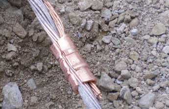
Photo shows crimping og a #6 Grounding Electrode Conductor to the main ground conductor.
Grounding Conductor Sizing
Conductor sizing is based on the possible fault currents that may be imposed in the conductor and the need to control voltages on various items until the overcurrent devices activate or for as long as the fault condition can exist.
More on Grounding
DC EGC (Equipment Grounding Conductor): The circuit that bonds together all the non-current carrying metal on the DC side of the system. This can include the module frames, mounting, metal roof, combiner boxes, DC disconnects, and the inverter. It usually connects to the inverter where the AC EGC then connects it back to the service entrance grounding bus forming a single EGC for the whole PV system.
DC GEC (Grounding Electrode Conductor): The circuit that connects the point of DC system bonding, the point where the grounded conductor is grounded in the inverter, to the premises grounding electrode system.
AC EGC: The circuit that bonds together all the non-current carrying metal on the AC side of the system. This can include the inverter, AC combiner panels, and AC disconnects. It connects back to the grounding bus in the service entrance.
These are all distinct circuits that serve a specific function in the PV system. These circuits can all use separate conductors or be combined to use a common conductor in a number of different ways. When combined the rules in 690 state that the requirements of all circuits have to be met by the conductor. So for instance a combined AC EGC and DC GEC has to be continuous because this is a requirement of the DC GEC even though the AC EGC does not have to be. A lot of people mess this up for instance when they break the conductor when landing in an AC disconnect.
In the average system the DC EGC goes to the inverter and the AC EGC then goes to the interconnection point and these circuits are combined into one EGC for the PV system. The DC GEC is run directly to the premises grounding electrode system. NEC 690 also allows the DC GEC and AC EGC to be combined so you don't have to run two conductors but only if the more stringent requirements of the two are maintained for the conductor run.
690.47(C)(3) allows the DC EGC and AC EGC to be combined
Combined DC Wiring
Visual inspection is the most effective method for troubleshooting/checking the combined DC wiring.
Inspect all visible connections, pull on the grounding cable to make sure that lugs are firmly attached. Conduits with circuits over 250 volts must be grounded either by ground bushings or connectors on metalic enclosures in non-concentric knock outs.
Inspect conduit couplings for possible separation.
Combined DC Wiring
NEC Requirements
690.8 Circuit Sizing and Current
690.9 Overcurrent Protection.
690.32 Component
690.33 Connectors.
ARTICLE 705
Interconnected Electric Power
Production Sources
(whole article applies)
Combined DC Wiring
DC array wiring size based on the procedures in the 2011 NEC, Art 690.8
Combined DC Wiring
The combined output of a combiner has the same requirements as the array DC wiring, except that this wire is not generally exposed to sunshine, but is in conduits. The conduits by be in sunshine and any heating effect needs to be considered in the wire size calculations.
Inverter
Troubleshooting
Inverters generally either operate or not at all, but there is the exception of some 3-phase inverters (Fronius in sequential mode) operating on two of the three power stages in the inverter. (The Fronius will have error codes for this.)
To troubleshoot a non-working inverter, first observe any digital display and/or indicators as this may define the problem. Access to a user manual is helpful. If there is no display or indication, measure the AC voltage either at the inverter output terminals or in the AC disconnect. If there is no AC voltage, the fault is in the wiring, other components, even with the utility service.
Check that the DC input voltage is within limits specified. There should be a label on the UL Listed inverter.
If input and output voltages are OK, check for a blown fuse in the inverter for the ground fault protection.
While the inverter is open to check the fuse, visually check for burnt parts. The smell test is useful for burnt parts.
If no obvious external problems are detected, contact the inverter manufacturer about repair/replacement. Field servicing of string inverters is not recommended.
Inverter
NEC Requirements
Inverters must be Listed to UL 1703 and be installed according to the manufacturer’s instructions.
The following NEC requirements are generally performed by the inverter:
690.5 Ground-Fault Protection
690.11 Arc-Fault Circuit Protection (Direct Current)
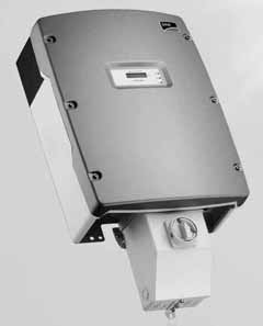
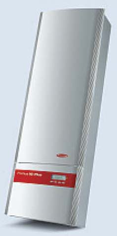
Typical String Inverters
Inverter Selection
Space is too limited in the web application to detail all the options for design of PV grid connected systems, but the basic outline is:
First, have a basic target of PV system size based on an analysis of energy needs, available array mounting space, financial resources, etc.
The energy need can be converted to a PV rating by use of computer programs and web resources. The array rating desired is the first part of selecting an inverter with this capability.
Next, the PV array has to be matched to the inverter by determining the acceptable series/parallel combination of specific PV modules that will meet this need. Then see if the array fits the available area, recycle as needed to reach a design.
The AC output rating of the inverter is used to calculate the required ampacity of the cables and balance of system components.
Inverter
This web page is limited to what the PV industry calls ‘string’ inverters. While there is no specific power limit, string inverters are generally rated for less than 15 kW). There are also ‘micro inverters’ that attach to one or two PV modules and these are not covered in this discussion.
In concept, inverters are very simple devices, they simply convert DC power into AC power and provide a status of their operation.
But the details are complex. The DC input must be within a usable and safe range, the AC output must be within specific voltage and frequency limits, and the inverter must shutdown when it is no longer connected to the utility (called an “anti-islanding” feature). Most inverters have the capability of detecting errors and displaying error messages and operating error indicators. Many inverters are capable of communicating their status to dedicated controllers and in most such cases onward to the internet. This is useful for troubleshooting.
The inverters all operate differently, so nothing beats having a user manual for details.
DC Disconnect
Troubleshooting
Generally not involved in troubleshooting. Check that all connections are tight.
DC Disconnect
NEC Requirements
690.13 Building or Other Structure Supplied by a
Photovoltaic System
690.14 Additional Provisions (Disconnecting Means)
690.15 Disconnection of Photovoltaic Equipment
690.16 Fuses
690.17 Disconnect Type.
DC Disconnect
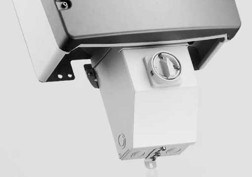
Typical DC Disconnect as part of an inverter.
DC Disconnect
The DC Disconnect switch must be rated for the voltage (cold open circuit voltage), PV current (short circuit of all parallel strings multiplied by 156%), and have a suitable enclosure (indoor or outdoor).
Some specific models of switches are Listed for each pole being suitable to a string of modules up to a specific voltage and current. Other switches require (or provide) wiring such that two or three poles are in series in order to be able to safely handle the high DC voltages. If a specific label showing one string per pole is not included in the switch, consult manufacturer’s data sheets.
These switches are generally unfused, but fused multi-pole safety switches can be used as DC combiners.
DC Disconnect
This can be either a safety switch or a switch that is built into the inverter or DC Combiner.
If a DC combiner feature is built into the inverter, The DC disconnect will be required to have multiple poles (one for each string) or multiple DC disconnects can be used (observe six-switch limit).
DC Combiner
About the only thing that can go wrong with a DC combiner is that the fuses can blow or fail. The best test for an open fuse is to measure the voltage across the fuse. More than about 50 millivolts usually indicates a problem. Open fuses have the difference between open circuit voltage and operating voltage.
DC Combiner
690.8 Circuit Sizing and Current
690.9 Overcurrent Protection
690.16 Fuses
DC Combiner
The DC Combiner must be rated for the system voltage, maximum current (short circuit * 156%) and usually for outdoor use. Most DC combiners used with string inverters use fuses in swing-out fuse holders because high voltage circuit breakers are very expensive.
DC Combiner
The design of the PV system may require more than one string of PV modules.
A DC combiner, or its function sometimes built into the inverter, is needed when there is the potential of back feed from parallel PV module strings that exceeds the value listed on the PV module for the maximum series fuse. See the description provided by the ‘Parallel String Calculation’ button.
The DC Combiner also provides a convenient facility for checking the performance of the individual strings.
Additional PV Array Strings
See the troubleshooting button for the PV Modules.
There is a detailed description on overall PV system performance available via the ‘Troubleshooting Help’ button on the main page of this web article.
PV Wiring
The use of the correct wire type is important for PV arrays. The wire must be rated as "Sunshine Resistant". Typical types are USE-2 and the newer PV wire type. Select a wire based on system voltage (i.e. up to 600V and Up to 1000V).
690.8 Circuit Sizing and Current
690.9 Overcurrent Protection.
690.32 Component
690.33 Connectors.
Additional PV Array Strings
The UL1703 Listing requirements require that the PV module be tested to withstand a continuous back feed as represented by the value listed on the PV module for the maximum series fuse. This value must be at least 156% of the rated short circuit current, but can be and is often higher. If the sum of the short circuit currents of the parallel module strings exceeds 156% of the short circuit current of a module, then fuses that do not exceed the value listed on the PV module for the maximum series fuse must be used for each string. When fuses are required, the rating of the fuse is used for calculation of wire size.
Additional PV Array Strings
The design of the PV system may require more than one string of PV modules. If there are parallel strings of PV modules, they should be identical in ratings of the module and orientation of the modules or a portion of the potential output will be lost due the mismatch (called mis-match losses).
A DC combiner, or its function sometimes built into the inverter, is needed when there is the potential of back feed from parallel PV module strings that exceeds the value listed on the PV module for the maximum series fuse. See the description provided by the ‘Parallel String Calculation’ button.
Troubleshooting the Grounding
Voltage checks-
First, if possible, check for AC and DC voltage on the PV array structure and module with respect to nearby equipment that should be grounded. The danger is contact between these systems. More than a few volts should be investigated and corrected.
Visual Inspection-
All PV modules and the supporting structure must be firmly grounded. Inspect all visible connections, pull on the grounding cable to make sure that lugs are firmly attached. Conduits with circuits over 250 volts must be grounded either by ground bushings or connectors on metalic enclosures in non-concentric knock outs.
Inspect conduit couplings for possible separation.
Some NEC references that apply
690.41 System Grounding.
690.42 Point of System Grounding Connection.
690.43 Equipment Grounding.
690.45 Size of Equipment Grounding Conductors
690.46 Array Equipment Grounding Conductors
690.47 Grounding Electrode System
690.48 Continuity of Equipment Grounding Systems
690.49 Continuity of Photovoltaic Source and Output
Circuit Grounded Conductors
690.50 Equipment Bonding Jumpers
The above references 250.134 or 250.136(A)
UL 2703 is a new standard for PV grounding and special products are now (2013) being listed to this standard.
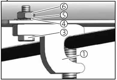
PV Module Grounding
This is a typical detail furnished by a PV module imanufacturer. The Lay-in lug is Listed for wet locations or even to the new UL 2703 standard.
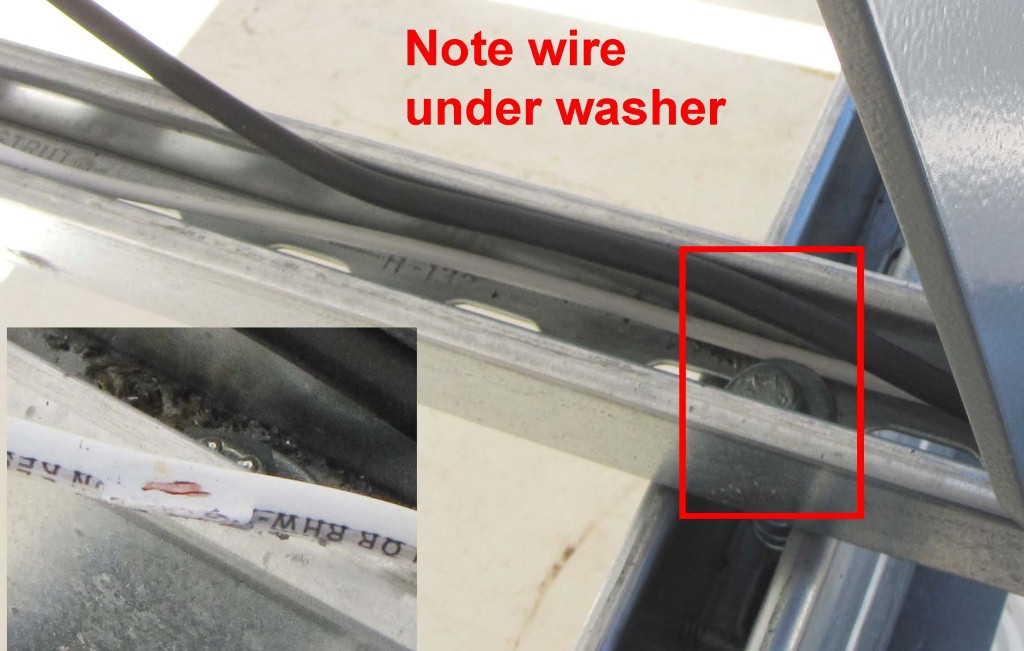
Here are some How Not to Do It examples:
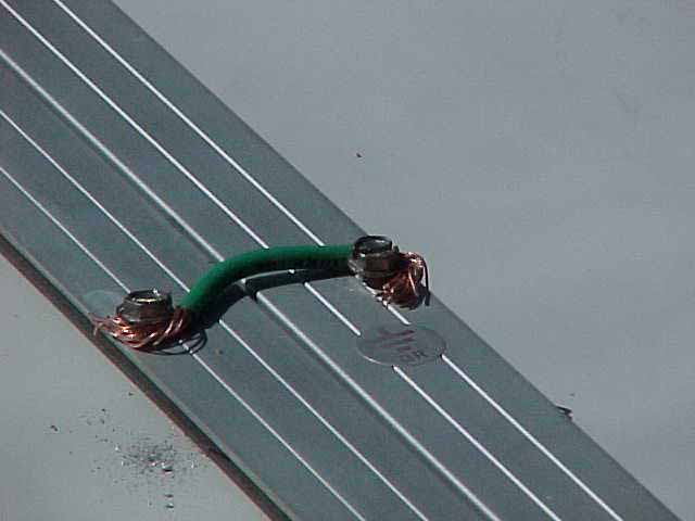
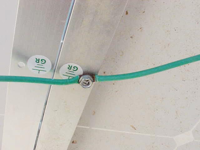
These How Not To examples are not using Listed lugs for the connection and the resulting copper to aluminum contact will cause severe corrusion.
The Equipment-Grounding Conductor Size is determined based on the over-current protective device per Art 250.122. Where no overcurrent protective device is used in the circuit (unlikely in a conforming grid-interactive PV system), an assumed overcurrent device rated at the PV maximum circuit current is used (125% of the short circuit current of the PV array).
OCPD Amps Ground CU AWG
15 14
20 12
30 10
40 10
60 10
100 8
200 6
300 4
400 3
500 2
Grounding
Both System and equipment grounding is required. System grounding is detailed in the inverter section since the inverter generally provides the system grounding function.
PV Array Grounding
All module frames must be bonded — lugs and wire are shown — but other methods, such as special clips, may be used. Devices (lugs and special clips or pads) identified and listed for bonding the metallic frames of PV modules are needed. See the Typical Photos button for a How Not To example.
Generally the array should be grounded such that removal of PV modules does not interrupt the grounding of any other PV module. When servicing a PV array check that the other PV modules have separate bonding, and if not, install a bonding jumper while the PV module or other equipment is removed.
It is highly recommended that anyone servicing a PV system first read Article 690 of the national Electrical Code.
See the Detailed Description for the Grounding Electrode Conductor (GEC) shown connected to the inverter.
Troubleshooting
There is a detailed description on overall PV system performance available via the ‘Troubleshooting Help’ button on the main page of this web article.
Most complaints of low performance will be due to the PV modules degrading or being dirty.
If there are multiple strings of modules, the first test is to compare the current of each of the strings and the open circuit voltage. This testing can best be done in the DC Combiner if there is one. Most DC Combiners have swing out fuse holders. Wear protective gloves and eye protection. The testing is best with two persons so that three hands are available.
First, measure the voltage on the PV module side of each fuseholder with respect to the common connection for the grounded polarity. If a fuse has failed (blown or open), that may be the source of the problem.
If a DC clamp-on ammeter is available, use it for the current tests, otherwise use a multimeter with an amps scare that exceeds the short circuit rating of the modules, place it across one of the fuseholders, then open the fuse to read the current. Be sure to close the fuseholder before removing the multimeter leads, otherwise a large arc can appear and burn the tip of the test probe.
If the currents are within about 10%, the open circuit voltage will have to be measured next. Open the DC Disconnect switch, then open all the fuseholders in the DC Combiner (or remove all PV input fuses from the inverter if the DC combining function is in the inverter). Measue the open corcuit voltages and compare. Any reading that are less than 90% of the highest voltage should be investigated, there may be open circuit PV modules or shorted by-pass diodes within the PV modules. It may be necessary to unplug the PV modules in the string to locate the defect.
PV Modules must be Listed to UL 1703 and be installed according to the manufacturer’s instructions.
690.5 Ground-Fault Protection
690.7 Maximum Voltage
690.8 Circuit Sizing and Current
690.9 Overcurrent Protection.
690.11 Arc-Fault Circuit Protection (Direct Current)
690.12 PV Arrays on Buildings Response to Emergency
Shutdown (expected in the 2014 NEC)
690.32 Component
690.33 Connectors.
690.51 Modules. Modules shall be marked…
690.53 Direct-Current Photovoltaic Power Source. (A
permanent label with ratings)
< PV Module
PV array below
PV Modules
Both the possible high voltage during cold weather and the lower voltage of hot PV modules needs to be considered. These limits MUST be in accordance with the specifications of the selected inverter.
Most inverter manufacturers provide web based information on the correct matching of specific models and manufacturers of PV module with their specific inverter models.
PV Modules
The PV modules are the key to PV system performance. The PV modules must have an electrical output that is compatible with the inverter and be installed with good access to sunshine.
Troubleshooting the wiring
PV system performance can be impacted by wiring problems. The wiring problems fall into two basic catagories, open connections, and ground faults.
Not all ground faults will be detected by the popular technique of referencing the grounded side of the array wiring to ground via a low capacity fuse, generally 3/4 or 1-amp. If the first fault is a ground fault on the grounded polarity of the array wiring, the fuse will not blow and be detected. No real problem exists until a fault develops on the ungrounded polarity. Then fault currents may exist without detection until damage occurs.
This fault was detected by a HiPot/Megger test before the array was placed in service.
PV DC wiring
690.8 Circuit Sizing and Current
690.9 Overcurrent Protection.
690.32 Component
690.33 Connectors.
ARTICLE 705
Interconnected Electric Power
Production Sources
(whole article applies)
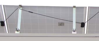
Typical rear of PV module showing module cables held tight to avoid rubbing in the wind.
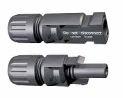
Typical PV module locking connector
DC array wiring size based on the procedures in the 2011 NEC, Art 690.8
1. 2011 NEC Art 690.8(B)(2) "Circuit conductors shall be sized to to carry not less than the larger of 690.8(B)(2)(a) or (2)(b).".
2. 690.8(B)(2)(a) Calculation is 125% x 125% of the sum of the parallel module short circuit currents without any additional correction factors for conditions of use (temperature, conduit fill, etc.).
3. 690.8(B)(2)(b) Calculation is 125% of the sum of the parallel module short circuit currents with correction factors for conditions of use (temperature, conduit fill, etc.).
4. Also, in many cases the temperature rating of the terminals at the ends of the wiring have to considered and may affect wire size. This calculation is based on 125% x 125% of the sum of the parallel module short circuit currents and the 30°C ampacity of the conductor using the 75°C ratings of assumed 90°C rated conductor to get the conductor ampacity.
The temperature of the conductors is affected by exposure to sunshine on the roof. [Table 310.15(B)(3)(c)]
PV DC wiring
Wiring exposed to sunshine must be rated for this exposure. Conduits and junction boxes must be bonded if containing conductors rated 250V (applies to both AC and DC systems) or greater. Note: Exposure to sunshine affects required wire size.
Understanding and Troubleshooting Grid Connected PV systems
Instructions on using this webpage
This page is interactive. Use the mouse to select a section of the 3-line wiring diagram for more information on that part of the PV system. As the mouse moves over a section, the background will change to highlight the selected section (scrolling the screen under the mouse us not recommended as it will result in several highlighted areas). For further information on a section, click on that section and a menu section with additional options will appear where these Instructions are presently shown.
This is a developmental version, many of the buttons for further information are not yet active.
PV System Notes
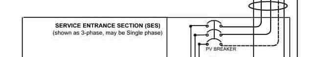
This Note section generally follows the wiring diagram on the left. The drawing illustrates a 3-phase system, but a single-phase system follows the same general design.
The allowed number of series modules depends on the inverter design and local low temperature values.
PV system grounding is very important. See the Grounding section immediately below the the PV modules on the diagram for more detail.
More than two module strings in parallel must have fuse protection per module listing. Fuses may be located in a DC combiner enclosure or in the inverter. DC disconnects may be separate, or part of the combiner or inverter.
Most inverters have the ability to display operational data and fault information on a digital display. A typical string inverter design is shown in this example. Note: There are other designs available, such as microinverters. The inverter may be marked for positive or negative ground (some PV modules perform better with a specific polarity). Note: No polarity is shown on this diagram. The inverter will likely have a fuse for detecting an array wiring ground fault. Some inverters do not ground reference either polarity of the array and use other methods to detect a ground fault.
A separate kWh meter may be included in the design to record the energy generated by the PV system.
Many electric utilities require the inclusion of a separate lockable AC disconnect switch that is readily accessible to utility crews. These disconnects typically do not have fuses, and access may be locked by an electric utility padlock. Some utilities require a separate GEC bond from the inverter to the main service ground.
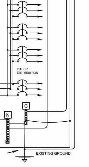
The drawing shows a load side connection of the inverter circuit to the service entrance. The circuit breaker is typically required to be on the opposite end of the distribution buss from the main circuit breaker and must be marked.
Labels specifying voltage and current values are required on many components in the system.
Refer to NEC Art. 690 for additional requirements.
PV System Notes
Instructions on using this page
Safety Warning
The systems outlined in this article use high DC voltages that cannot be simply turned off. This discussion is limited to test techniques that do not require disassembly of the PV array, but there is some exposure to terminals within the equipment that will normally have high voltages. Any work on roofs requires fall protection for safety.
Copyright 2012 Photovoltaic Resources International
All rights reserved
Troubleshooting Help
Troubleshooting a non-working system
Typically, you'll be contacted by the owner of this type of system when it has stopped working. Most times, this is due to one of these five problems:
1) The inverter is no longer connected to AC power within the normal limits of voltage and frequency.
2) The inverter may have detected a ground fault on the DC side of the system.
3) The inverter may have failed.
4) Either the inverter, disconnects in the AC circuit, or breakers in the AC circuit may have been turned off.
5) A fuse in the system has failed.
Many string inverters have a simple digital display and a few LED indicators to show system status. Check these first and correct any external problems. If the inverter appears totally non-functioning, check the AC power circuits and measure the voltage across the output terminals of the inverter. An absence of AC voltage indicates a problem with the AC circuit. Fuses might have failed or breakers in the AC circuit may have been turned off. It is unlikely that the frequency of the power system has caused the outage. Inverters should be listed to UL 1741 and have a label that indicates the acceptable AC and DC voltage ranges the unit can operate within. If you do find AC supply voltages that are out of specification, notify the electric utility of the problem.
If the inverter indicates a ground fault condition, this is a little more difficult to address. It also requires you to follow safety procedures to limit your exposure to the potential high voltages of the array. On one hand, the situation may be transient, due to moisture or pressure on wire insulation that is not normally present. But often, the fuse in the inverter (usually a 1A, but check the manual or markings in the inverter) has failed. If so, replace the 600VDC fuse (verify proper size by referring to the inverter manual) and follow the reset procedure outlined by the manufacturer's instructions.
If the system has more than two strings of PV modules, there should be fuses for each string. They will be located in the inverter or in a separate DC Combiner enclosure. Turn off all switches (DC and AC) and use an insulated tool to snap open all DC fuse holders. (Warning: there is a possibility of a long arc appearing if a ground fault is located between the DC combiner and the inverter, or within the inverter itself.) If a long arc does appear during this operation, close the fuse holder quickly and cover the entire array with opaque material so the system stops producing electricity. At this point, it is now safe to start opening the DC fuse holders again.
Once all fuses have been removed, go ahead and remove the opaque material you placed on top of the panels and measure the voltage output of each string. A string with a ground fault will have a lower voltage. If a ground fault is not detected, use a high voltage resistance tester to check all wiring and the PV modules. The general procedure is to isolate all wiring from ground and test all circuits. (Caution: the inverter must be isolated as it may be damaged by the high voltages of resistance testing.)
Most UL Listed PV modules are rated for use in systems up to 600VDC and can withstand test voltages of twice that voltage. The typical test procedure is to connect the negative lead of the tester to ground and the positive lead of the tester to the negative lead of a string and test at 500V. A new system with good insulation should indicate more than 2,000 MΩ, however, readings greater than 200 MΩ are acceptable. Lower values should be investigated by disconnecting modules and testing parts separately until the source of the low reading is pinpointed.
The inverter manufacturer may have to be consulted if there are other error codes displayed on the inverter. Some inverters have fans that can fail and this may be indicated by either a fan fail code or a high temperature code.
Handling poor performance issues
It is often hard to distinguish between real and perceived performance issues. Many string inverters have displays that indicate power output in watts. You might expect that on a clear day at noon the display will equal the rating of their PV array. But this is not true because the ratings are at 25°C and the sunshine on the PV array will warm the PV array to well above 25°C.
To determine if a PV system is performing as intended requires the use of either special equipment, which can measure the solar irradiance on the PV array and the module operating temperature, or a study of the available performance data. The study method requires the measurement of the energy (kWh) produced over a specific period and comparison to system energy specifications. Many inverters display the accumulated energy delivered to the electric utility system, and systems may have a kilowatt meter on the inverter output. The recording of these readings over a period of time will provide the energy produced per day by the PV system. This can be compared to either the system's energy specifications provided by the original installer, or to energy calculations made over the same period using either custom software or the National Renewable Energy Laboratory's publicly available PVWatts calculator (www.nrel.gov/rredc/pvwatts). Even on a poor solar weather month, the output of the PV system should be within 15% of the predicted output for the location and system specific hardware.
Direct measurement of irradiance on a PV array requires a calibrated pyranometer or reference cell and a means of measuring operating cell temperature. The use of a handheld infrared temperature sensor typically produces an acceptable measurement value. Measure operating DC voltage and current with a clamp-on DC ammeter. Calculate the DC power output. Then, correct for irradiance (1,000 W/m² is reference irradiance), correct for cell temperature (-0.5% per degree C from 25°C is a good estimate if the PV module temperature coefficient is not available). Compare results to the PV array power rating.
If the above calculations indicate a performance problem, then you should turn your attention to one or more of the following areas:
• Dirt or shadows on the array are limiting PV module performance. Generally, the least illuminated section of a
module or string of modules affects the total string output.
• Inspect for module problems such as cracked cells, open cell-to-cell connections, and shorted bypass diodes.
Be aware these problems can be difficult to identify in the field. Most PV modules use special connectors
that do not expose the live parts for measurements while connected, making it difficult to test individual PV
modules. If a PV module failure issuspected, contact the manufacturer and inquire about any long-term
warranties that might be in effect.
• Look for melted plastic in the junction boxes. Some modules have been recalled due to connection problems in
these boxes.
• The PV array may be incorrectly wired. Make sure all strings have the same number of modules, or check
voltages in the DC combiner enclosure with the system off and the fuseholders open.
• Inspect for open fuses or loose connections in the DC combiner enclosure
• Inspect the inverter and focus on these areas:
• The inverter may have multiple power sections and one may have failed in a manner not detected by the
main inverter controller. This type of inverter will operate correctly at lower power levels, but limit total
operation of the system.
• Inverter fan or ventilation failures (check for blocked filters) may also limit operation at high power levels.
• Look for conduit fittings that may have become separated due to thermal cycling and wind.
• Check for loose connections that may allow water to enter the conduits or other system components.
Explore PV Systems
Explore PV Systems


Introduction
Photovoltaic (PV) power systems are becoming very common as the cost of these systems is declining and the availability of incentives that further lower the costs. The technology is supported by codes and standards (NEC Article 690 is the main code), Listed equipment, and training programs that should result in safe and reliable systems. Most systems are installed and maintained by companies specializing in the technology, but other electricians are called upon to service and/or work on related wiring of these systems.
This article is intended to provide some guidance to persons who need a basic understanding of these systems in order to check out a system that may be non-performing or under-performing. This article covers one of the basic types of PV system, string inverter based systems that use a single inverter to connect PV modules to the utility grid without any battery backup. There are other designs such as micro-inverters (one inverter per PV module) and systems with multiple inverters or large utility scale inverters.
Basic System Design and Operation
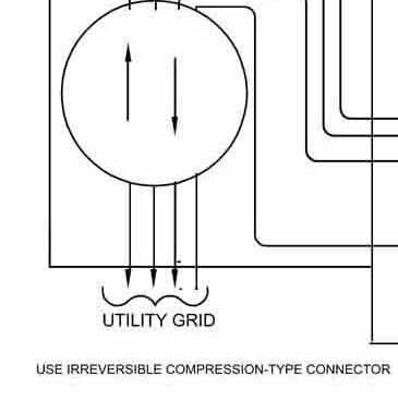
The PV industry uses some terminology that is not common. PV modules are the basic building block and generally consist of PV cells laminated behind glass and encapsulated with insulating materials and mounted in a frame. There are other designs that are flexible and are adhesively mounted to metal roofs. And assembly of modules on a mounting frame is a panel, and the complete assembly of modules/panels is an array. An inverter is used to convert the DC power from the array into controlled AC power suitable for connection to the utility grid. Other wiring components are involved.
The figure on the main page shows the basic 3-Line diagram of a PV system of the design generally called ‘String Inverter’ where one or more series strings of PV modules are used to generate the higher voltages (250-500VDC is typical) needed by these inverters. The text next to the diagram describes the function of the components and some of the special considerations.
These systems function automatically and do not require any user or owner interaction. If the utility power is interrupted or is not within the normal limits of voltage and frequency, the system will stop operating until the utility returns to stability within these limits. The inverters are designed to detect a ground fault within the PV array and associated components and cease operation.
Click on the 'Explore PV Systems' button above to learn more about PV systems.
Need to insert images here
Explore PV Systems
Introduction